This page describes the building and design of a guitar amp using subminiature tubes and a switching power supply.
Warning! This page describes circuits dealing with high possibly fatal voltages. Don't attempt to build the describes circuits unless you know how to follow appropriate safety procedures. If you don't know what I'm talking about now, then you should not attempt this project.
Design of the preamp is loosely based on a Marshall 18 Watt, here implemented with an additional gain stage (V2a) and using 6021 subminiature dual-triodes. It is a typical design found similarly in other tube guitar amps. In the current configuration the preamp has a lot of gain but is not capable of delivering loud clean tones. With humbucking pickups it is probably impossible to avoid distortion unless the guitar volume is turned down.
Output amplification is produced by one half of a 6021 subminiature dual-triode. This tube can be biased to 1 W according to its datasheet. While this may not seem like much it is enough to annoy your neighbours and way too loud for late night playing.
The one-knob tone control works reasonably well though I mostly put it on a sweet spot at about 11 o'clock and let it set there.
|
R8 R9 R10 R11 R12 R13 R14 R15 R16 R17 |
1M 68k 100k 750R 100k 68k 100k 1k 270k 270k |
R18 R19 R20 R21 R22 R23 R24 VR1 VR2 |
39k 100k 680R 100k 350k 12k 820R 500k log 500k log |
C9 C10 C11 C12 C13 C14 C15 C16 C17 |
4n7 500 V ceramic 10n 630 V film 1u 16 V electrolytic 330p 500 V ceramic 10n 630 V film 4u7 16 V electrolytic 10n 630V film 2u2 16 V electrolytic 100u 16 V electrolytic |
C18 C19 V1 V2 T1 J2 J3 |
22uF 16 V electrolytic 22uF 16 V electrolytic 6021 dual-triode 6021 dual-triode Fender reverb transformer #22921 mono audio jack mono audio jack |
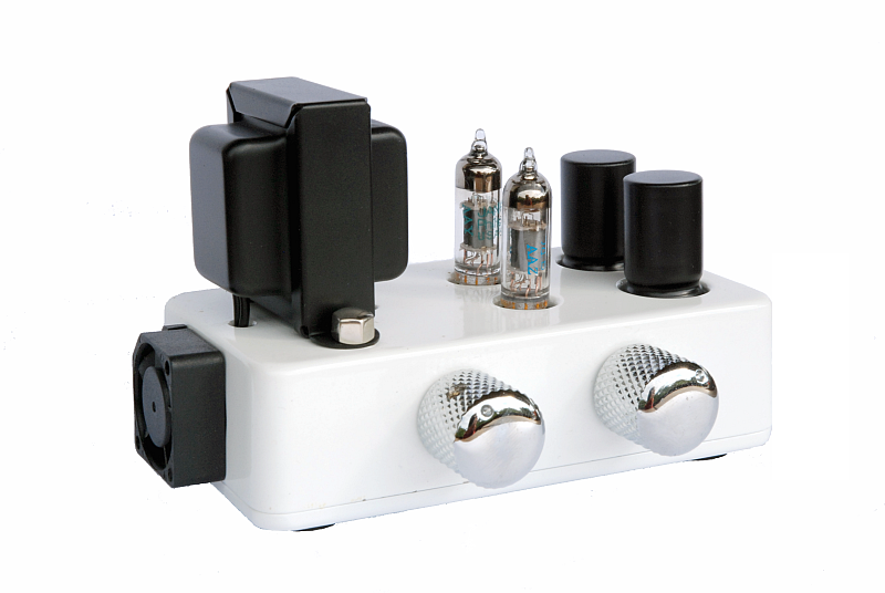
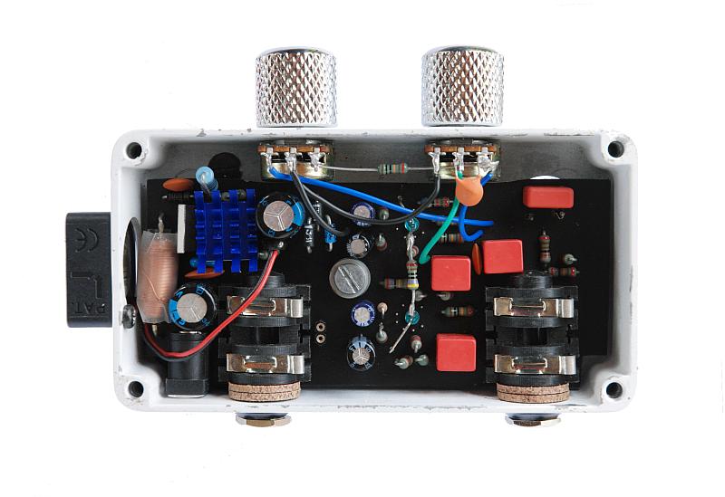
The output transformer is a replacement part for a Fender reverb transformer. It is rated for 3.5 W and has an impedance ratio of about 2800:1. Normally this transformer has leads that extend from its back. I didn't like the look of that and changed them to come out of its underside. After rewiring I closed the original holes with filler for automotive repair and sanded the transformer to a smooth finish. Then it was spray painted flat black.
The built-in piezo speaker is harvested from a dead laptop computer. Its high frequency response is really ear-piercing, so it must be tamed by two capacitors connected across the speaker terminals (forming a non-polarized electrolytic capacitor). It is automatically connected through the switching terminals of the output jack when no external speaker is present.
This amplifier uses a DC/DC converter in Boost topology  . Roughly
said it operates on the principle that an inductor responds to changes in current by
developing a voltage across its terminals. The faster the change in current, the higher the
voltage. This voltage is then stored in a filter capacitor. Diode D1 prevents the capacitor
from discharging back through the inductor. Usually the switching MOSFET is controlled by a
pulse-width-modulated (pwm) signal that determines the input/output voltage ratio. Since
space is tight on the circuit board no pwm logic is present. I think this amp can live
without regulation since the input voltage is fixed due to it being the heater supply (12.0 V
- 13.0 V) and the property of a class A amp to draw a fixed amount of current. If dedicated
switching regulators in a reasonable size would have been available I would have tried one
though. DIY solutions with discrete components often not only change the pulse width but also
the frequency. Due to the highly varying behaviour of the inductor to different frequencies I
find this option not viable.
. Roughly
said it operates on the principle that an inductor responds to changes in current by
developing a voltage across its terminals. The faster the change in current, the higher the
voltage. This voltage is then stored in a filter capacitor. Diode D1 prevents the capacitor
from discharging back through the inductor. Usually the switching MOSFET is controlled by a
pulse-width-modulated (pwm) signal that determines the input/output voltage ratio. Since
space is tight on the circuit board no pwm logic is present. I think this amp can live
without regulation since the input voltage is fixed due to it being the heater supply (12.0 V
- 13.0 V) and the property of a class A amp to draw a fixed amount of current. If dedicated
switching regulators in a reasonable size would have been available I would have tried one
though. DIY solutions with discrete components often not only change the pulse width but also
the frequency. Due to the highly varying behaviour of the inductor to different frequencies I
find this option not viable.
Attention! I build this amp as it is seen here, but if you
decide to build one for yourself please consider that the power supply is a very simple
design and not entirely safe.
You should not try to recreate it according to the schematic provided here alone. Please
consider adding another safety mechanism besides the zener diodes. Something like the method
used in this Nixie
tube power supply will do the trick of limiting the voltage in a more safe manner and
requires only minimal additional parts. I will update the page after I have experimented more
with the circuit.
I said so on top of the page, but here it is again: There is no
chance you can build this amp safely if you are new to electronics or tube amp building. High
voltages are deadly and with the switching supply their is always uncertainty as to how high
the actual voltage will turn out to be.
The switching pulses are generated by an NE555 timer IC (must be the bipolar version, the MOSFET one cannot drive the switching transistor) running in astable mode at 95 % duty cycle and about 100 kHz for an output voltage of 230 V at ~15 mA. Input voltage would ideally be 12.6 V because this is the nominal heater voltage for the two series-connected tubes. 12.0 V input works and is what I am using. The wallwart must be capable of sourcing 1 A of continuous current. Peak current may well be a lot higher. I recommend a regulated supply to avoid buzzing from a not sufficiently filtered heater voltage.
|
R1 R2 R3 R4 R5 R6 R7 |
120R 470R 39k 2k2 50R 2 W 270k 8k2 |
C1 C2 C3 C4 C5 C6 C7 C8 |
1000u 25 V electrolytic 1000u 25 V electrolytic 330p mica 10n ceramic 1n 500 V ceramic 22u 350 V electrolytic 22n 630 V film 22u 350 V electrolytic |
D1 D2 D3 D4 D5 D6 |
blue 3 mm LED blue 3 mm LED UF4004 100 V 1.3 W zener 100 V 1.3 W zener 75 V 1.3 W zener |
L1 Q1 IC1 J1 Fan |
3300u 0.5A rf suppression coil IRF740 NE555 DC plug 25x25 mm 5 V brushless DC fan |
The inductor I used is no special part, but a usual RF suppression choke. It works well and is easily obtainable. The value was found out through several tests with different sized inductors and operation frequencies. I finally settled on a combination that would give me roughly the desired voltage and current while not drawing excessive current by itself. Important factors in choosing this coil were foremost availability and a low series resistance (high amperage rating). The inductivity is not that important, it should work with a ten times lower value as well.
For the diode I settled on a UF4004 fast recovery rectifier. The high operation frequency makes it impossible to use a general purpose rectifier (1N400x). The switching MOSFET is an IRF740 which got a very low on-resistance (less than 0.5 Ohm) and low capacitance making it suitable for high frequency switching.
To prevent voltage runaway when no load is connected, e.g. when the tubes are warming up or when no tube is installed / one tube has an open heater wire, the maximum voltage is limited by two 100 V and one 75 V zener diodes rated for 1.3 W each. They should provide enough protection for the short time till the tubes start conducting but may fail after a couple of minutes without tubes installed since they get quite warm. Under normal operating conditions they don't affect the output voltage.
Due to the high switching frequency and the square and triangle shaped waveforms produced, there are a lot of higher order harmonics present in the high voltage supply line. These pose no problem to the sound quality since they are well above the audible range, but they produce radio frequency interferences. I think the long PCB trace from the diode to the filter capacitor acts as an antenna, too. Before I installed the small 1 nF ceramic capacitor to ground (C5) right after the diode there was so much radiated EMI that digital TV reception through my room antenna was completely blocked out when the amp was on.
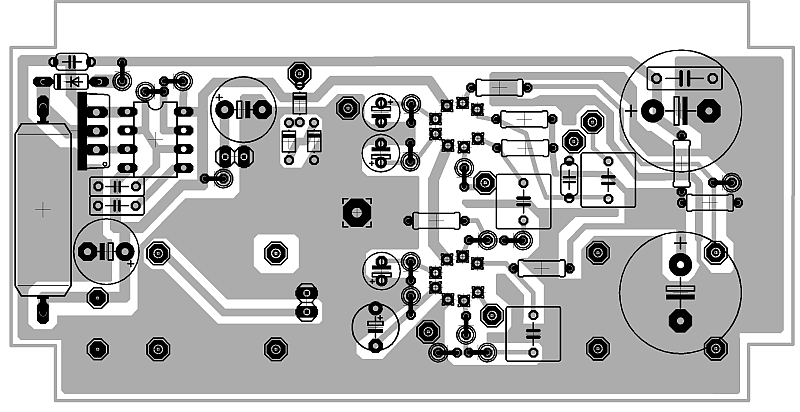
Note: The position of resistor R6 is different in the schematic and in the layout i posted below. R6 is used only as a bleeding resistor, that means it's purpose is to drain the power supply capacitors when the amp is powered off. Because of this and the in comparison low value of R7 is may be installed either according to the layout or the schematic without detrimental effect.
The circuit fits on a single sided board with the tubes and the filter capacitors as well as the transformer leads mounted on the solder side. Improvised sockets are used for the tubes. They consist of eight connectors from low profile IC sockets. Every other of them is isolated with heat shrinking tube. Here you can see a close-up of a socket.
It is a good idea to stabilize the filter capacitors in some way. They do easily bend when touched and can lift their copper pads from the board. This actually happened to me, putting the full B1 voltage on the capacitor case after breaking of the ground connection.
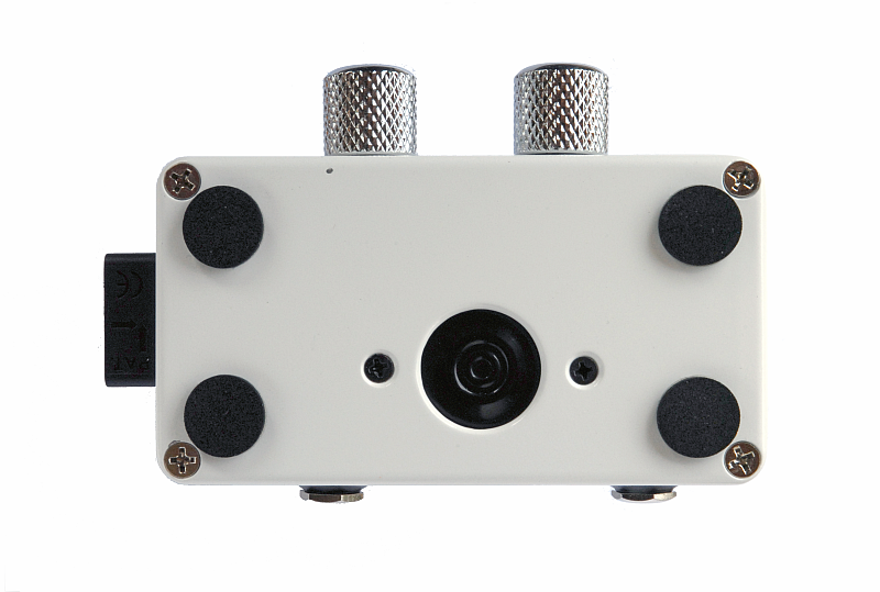
Grounding to the aluminium chassis (Hammond 1590 B) is done through the screw you see in the middle of the circuit board. The corresponding nut is glued to the case. Apart from grounding this serves another important function: it holds the board parallel to the topside of the case. If the board was only held in place by the input and output jacks it would be at an angle because the sides of the box are not perpendicular to the top, but slightly slanted.
The small fan is necessary to keep the temperature of the switching MOSFET and the inductor down. A small heatsink (for memory cooling, leftover from my graphic cards fan kit) is installed on the NE555 IC but it's not really necessary.
From the fan a constant but very low volume whining sound is introduced into the speaker signal. Apart from lowering the rf interference C5 also lowers this whining considerably.
Care must be taken that the IRF740 MOSFETs casing does not make electrical contact with anything since it is connected to the transistors drain terminal. This means the casing is basically on the same voltage as the plate supply B1. If a heatsink is to be connected to the MOSET it must be isolated with a rubber pad and a special plastic washer for the mounting screw.
Development of this amp went through many stages. I considered and tried out some other solutions on the way to this for once final design. Some of the ideas may seem silly now, but they appeared completely reasonable back then.
At first I had the same basic layout as now, but the cathodes were both aligned to the back of the amp which gave me some layout advantages but also made a lot of problems with the heater wiring. I also only had one big 100uF filter capacitor which of course led to oscillation due to insufficient decoupling of even phased gain stages. At that time I thought I could keep oscillation down by interstage voltage dividers only, while keeping the one capacitor approach.
Then I switched to a three tube layout because I figured that two tubes had already been done several times and I had some spare space on the board. The question remained what to use the two additional gain stages for and where to get the heater voltage (6.3 V) for the new tube? For the heater voltage problem I decided to connect a resistor paralleled with the fan in series with the new tube. This worked fine except for some whining from the fan motor. For the third tube I also played with the idea of using a power pentode. All I had available at that time was a 5639 RF amplifier tube. It is actually pretty similar to the 5902 I used in my class AB amp. Of course this tube was heavily mismatched to the transformers primary impedance, but I tried it anyway. Results were unfortunately not at all convincing: a lot of noise, heavy oscillation, bad overall tone. If you really insist, here is a picture of the three tube prototype (warning: bad quality cell phone image).
After this I reconsidered the two tube version. To make it more "exciting" I wanted to add an effects loop. Maybe this would have actually been possible using a stereo plug and a y-cable for send and return. Of course the effects loop should be buffered and parallel to allow mixing of the dry and wet signals. For the buffering I considered OpAmps or FETs. Half-way through the decisions process it finally occurred to me that an effects loop just doesn't make much sense in an amp that is supposed to overdrive the output tube most of the time. Normally the fx loop is used so that the preamp distortion doesn't mud up the time based effects (reverb, delay etc.) plugged into the amp. With it both preamp distortion and effects are possible. Poweramp distortion is always added to the effects, but with modern high powered output stages and high gain preamps, it is actually not often to be found. In this amp overdriving the output stage should be a key element in the sound, so I scrapped the loop idea again.
In the end all these failures led to the current bare-bone implementation. Two tubes, separate filter capacitors for pre- and poweramp and a different board layout (all cathodes pointing to the left). I also chose the 18 watt style tone control over the before used Marshall style tone stack. The coupling capacitors were also replaced with 5 mm grid types.
Click on a picture for a larger version.

Please send questions and comments to electronics@jjs.at.