When dealing with 90's computers, especially from IBM there is a high chance to encounter Token Ring network cards. This technology is now obsolete to the point that it is no longer possible to just attach such a network card to a modern networking environment. Unlike Ethernet, Token Ring is not intended to be used without a router- or switch-like device, which complicates matters. Especially connecting two PCs equipped with Token Ring together just using a cable is not possible. A connection always requires a Multistation Access Unit (MAU). This device handles the physical insertion and removal of network devices from the ring making up the Token Ring network. As an additional complication, instead of RJ45 connectors, especially older cards use a DB9 connector for the network on the PC side and a proprietary IBM connector on the MAU side. Both the increasing rarity and cost of the required devies (MAU, cables) or even the components to DIY a replcement led to the creation of a workable, but not entirely perfect MAU for hobbyist use.
The MAU serves two functions: ring insertion of a node and isolation between nodes. The main components used for these purpuses are a relay and a transformer with specifically set-up windings. Connection between the network card and the MAU consists of two differential pairs for Rx and Tx data.
Before a card inserts itself into the ring it performs a test of the cable using the normally closed relay path as a loopback. This is also the reason why the MAU is strictly necessary and cannot be replaced by a hard-wired connection. The card has to be able to do both the loopback test and the communication after insertion. The network card can trigger the insertion into the ring by applying a common mode voltage between the Rx and Tx ports. This DC voltage can be detected and filtered out in the MAU through the transformers and used to either directly drive the insertion relay (such as in an IBM 8228 passive MAU) or to enable a dedicated insertion circuit (e.g. in an IBM 8226). Token Ring transformers are in general hard to find or expensive parts because their setup is unusual in that they have two separate primary windings instead of the much easier to obtain version with a center-tapped winding. This part is being replaced here by capacitors for isolation (C2 to C5) and an opto-isolated circuit to detect the common mode voltage. The commmon mode voltage is extracted simply by summing up the differential Rx (through R1 and R2) and Tx (through R3 and R4) signals respectively and driving the optocoupler input with the resulting voltage differential. The relay used for insertion could be a 4PDT relay that has all required switches built in but it is not necessary. Here two 2PDT communication relays are used instead. The LED on board will light up when the relay is switched on, therefore signaling that the respective node is inserted into the ring.
Connection between the MAU and the network card is made through a standard 1:1 DB9 cable as used by a PC serial port. With the male connector on the MAU, a standard serial port cable (not null-modem) is all that is needed to create the connection. This will of course not have the same signal integrity as the official solution. Neither is the cable impedance controlled nor is there any cable shielding or even routing of the signals as twisted pairs because the serial port cables are not made that way. Despite that no connection issues were observable with 2 m serial cables between nodes and the MAU using 16 MHz link speed.
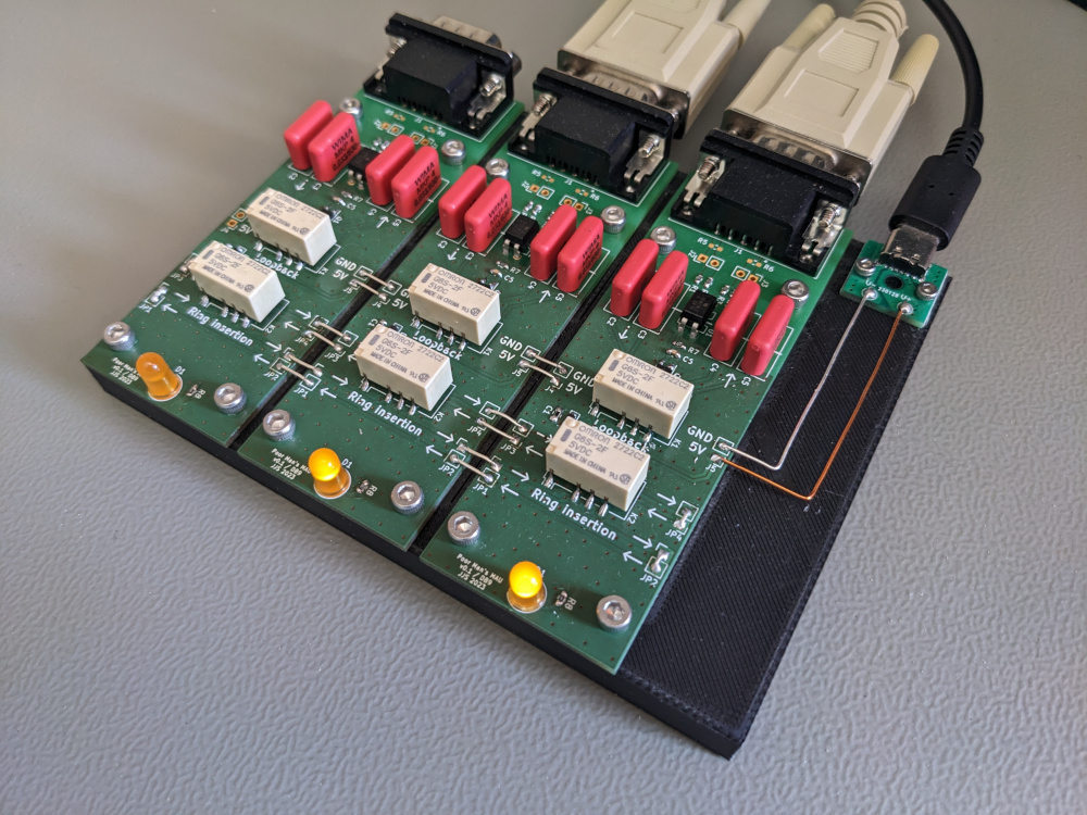
This project is set up so that a single node is implemented on a PCB. There are jumpers on both sides of the PCB that can be used to either loop back between Rx and Tx on the same board (if it is the only board or the last board in the chain) or to patch through to the next board. 5 V and GND can also be chained between boards, but no power supply circuit is provided. In the finished board depicted below, 5 V is taken from a USB-C breakout board. The current requirement is essentially the coil current of the two relays, so for the parts used here about 50 mA per board if that node is inserted into the ring.
An alternate untested version using a RJ46 connector is provided. This one could be used with a standard Ethernet cable. It should also be possible to mix this board with ones using the DB9 connector to build a more versatile MAU.
Click on a picture for a larger version.
KiCAD 7 project file, schematic and PCB.
poor_mans_mau_db9_v0.2.zip (91 KiB)
poor_mans_mau_rj45_v0.2.zip (with RJ45 connector, untested, 95 KiB)
Please send questions and comments to computing@jjs.at.